Tampilkan postingan dengan label keel. Tampilkan semua postingan

Boat Plans Nz | What about keel shapes and keel bulb design

| 0 komentar |

Boat Plans Nz


The Star 45 R/C Model Sail Boat - Builders Journal

"Dave Mainwaring"
Someone asked about shapes and sizes.

I like keels that resemble in some manner the "Scheel Keel". Flat bottoms help fight heeling. My version was based on my sailing in waters with lilies and pond grass that snagged torpedo shaped bulbs. I liked being able to back away and have the crap slide off the keel.


http://photos1.blogger.com/blogger/5587/620/400/Sirius%2045%2006.jpg


http://photos1.blogger.com/blogger/5587/620/400/Sirius%2045%2002.jpg


Here is a photo of the original Mainwaring Keel and Mainwaring Bulb


http://photos1.blogger.com/x/blogger/5587/620/400/353321/Sirius45Keel.jpg


Do you find information about Boat Plans Nz are you looking for? If not, below may help you find more information about the Boat Plans Nz. Thank you for visiting, have a great day.
Read More..

Boat Plans And Kits | New rig for Didi 29 Retro

| 0 komentar |

Boat Plans And Kits


The Didi 29 Retro was commissioned by a client in Cape Town, to build for himself for competition in the classic yacht races in the Caribbean. He wanted a boat with modern underbody and appendages but with a large gaff rig of classic configuration, to race in the modern classic division.
Underbody of Didi 29 Retro
Last year I was asked to draw a more conservative cruising gaff rig for the design, to better suit those who have no aspirations to race with a big crew or simply want to cruise. That resulted in the cruising gaff rig with about 20% less sail area on the same foretriangle height.
Didi 29 Retro racing gaff rig at left, cruising rig at right
This year I was asked to draw a more modern rig for it, which developed into the squaretop Marconi rig. This one will better suit most sailors, being easier to handle and easier to understand for those who dont know gaff rigs. On sail area, it fits between the two gaff rigs and it will be interesting to see how the three compare on the water.
Didi 29 Retro with squaretop Marconi rig
The squaretop Marconi rig suits the aesthetics of this hull rather well. It would be my choice if I were building this boat for myself. Should be an exciting boat to sail too, able to take advantage of the power of modern stable sail fabrics.

To see more of this and our other designs, go to http://dixdesign.com/

Do you find information about Boat Plans And Kits are you looking for? If not, below may help you find more information about the Boat Plans And Kits. Thank you for visiting, have a great day.
Read More..

Plywood Boat Plans | Star 45 R C model sail boat Keels and keel ballast bulbs

| 0 komentar |

Plywood Boat Plans


AMYA Star 45 Class Rules, 2006, KEELS AND BALLAST BULBS


7.1 Keel will be of the style known as drop, and will be of the FIN and BULB type.

7.2 Keel fins may be solid or hollow and constructed of reinforced plastic, plastic laminates, fiberglass, wood or metal. (Note: Strength and integrity of the keel fins must be maintained whether built solid or hollow.) Keel fin shape is not specified but must follow the general shapes outlined on the reference drawing. However, keels will not be less than 6 inches nor more than 8 inches long (Fore and Aft) at the keel/hull junction, nor less than 4 inches nor more than 6 inches long (Fore and Aft) at the keel/ballast bulb junction.

7.3 Keels, keel fins and ballast bulbs may be removable, however, they may not be changed, interchanged, substituted or otherwise manipulated once any heat or series of heats in which scores will be compiled, has started. Mechanically movable keels or ballast bulbs are specifically prohibited from use in Star 45 Class Yachts.

7.4 Ballast bulbs may be constructed of any material not prohibited by the AMYA. The actual shape is left to the builders discretion, but will not exceed 9.75 (9 3/4) inches from the front of the keel bulb to the rearmost point of the keel or bulb.

7.5 Total drop (length) of the keel fin/ballast bulb combination will not exceed 11.5 (11 1/2) inches when measured from the keel/hull junction, before any fillers or streamlining is added.

7.6 Ballast may be made from any readily available material, such as poured lead, lead shot, etc. (Note: When using material such as lead shot, the mass must be solidified through the use of a bonding agent such as fiberglass or epoxy resin, plaster of paris, poured over and through in order to create a solid mass.)

7.7 Race directors may elect to use a template based on the construction plans to determine the keel length (depth).

7.8 Keel depth shall be measured from the center of the keel fin at the hull to the bottom of the ballast bulb. This measurement is from the edge of the bottom of the hull as it meets the side of the keel and should be determined during construction and before any fillet or fairing is added.

7.9 The Star 45 Class specifically excludes radio equipment, sail controls and batteries (power cells) from being considered ballast. This specification defines ballast as anything carried aboard the model for the main purpose of changing the weight distribution of the model and/or weight of the model. Ballast shall be fixed in place by gluing, fiberglassing, or bolting (bolts and screws).

7.9.1 Ballast may not be removed or relocated during any one regatta. The use of Velcro or similar quick release fasteners is prohibited as methods of mounting ballast.


Do you find information about Plywood Boat Plans are you looking for? If not, below may help you find more information about the Plywood Boat Plans. Thank you for visiting, have a great day.
Read More..

Boat Plans Catamaran | Sea Chest Final Resting Spot

| 0 komentar |

Boat Plans Catamaran


OK, Im getting kind of tired of the re-work, but I had to move my sea chest location once again. I had abandoned the first location as the intake was to small, increased the size of the intake and moved the sea chest to the area in front of the generator. After doing some assembly, I realized that the sea chest was going to be to close to the water line, and I want it a below the water line. I also felt that having it in front of the generator was going to be a pain in the ass, and Im sure Id be regretting it years down the road as I banged into it while servicing the generator. So, as much as it pained me, I moved the sea chest again. I turned it 90 degrees, and moved it another foot away from the generator.

During my recent visits to the scrap yards ( selling scrap metal), Ive been scrounging around for some for some 2" 316 stainless. No luck on finding some, so I had to break down and make a small purchase of some new material. Making sure all my parts were 316L was important to me so having to buy new material was not such a bad thing given I could assure quality.

The first line of business on the sea chest was building the manifold. I used a 12" piece of 2" along with two 1" x 4" nipples. I cut the nipples in half on my lathe so I ended up with the four pieces needed for my valves. Using a hole saw, I bored four holes in the 2"x12" nipple so I would be able to weld in the valve stubs. I was going to use a boring head to make the bores, but the hole saw did just fine by using the micro feed on my mill and running water on the bit to keep it cool.

Welding the 1" nipples in the manifold was pretty easy. I stood the 1" stubs on the work bench then lowered the 2" manifold on to the stubs and held the manifold up with blocks. This way I was able to keep the stubs plumb, level, and square with the manifold without having to come up with a clamping contraption. I tacked the stubs in place, then placed the manifold in the vice and welded her up. I made two passes around the each stub. I air tested the manifold to 40 psi and Ill be damned if it passed on the first try.

I bolted the stainless flange to the flange I welded into the hull, and just for kicks I tested to see if they were electrically isolated. The electric isolation test was good.

Ive yet to find a used 2" sea strainer, so Im unable to finalize the assembly. Im going to need to brace the manifold both vertically and horizontally, but I cant make the brace until I know the final location of the end after the sea strainer is in place. I also think I can lower the manifold 2" by using a close nipple vs the 4" nipple I have between the ball valve and the "T". Im going to keep my eyes open for another valve that with an overall length of 4" vs the 6" valves I have now. I really cant finalize any of this until I I have a sea strainer.

Im very happy with how the sea chest looks, and more happy with its location. This set up will be extremely easy to service and bring various water intakes on or off line as I need them. I went with a "T" vs a 90 on building the sea chest in case I had to blow a clog out of the intake while under way. I can screw a nipple down in to the "T" to get above the water line, and clear any thing away without having to get into the water. If I had used a 90, cleaning from the inside would be difficult at best.

Do you find information about Boat Plans Catamaran are you looking for? If not, below may help you find more information about the Boat Plans Catamaran. Thank you for visiting, have a great day.
Read More..

Boat Plans Aluminium | Star 45 Mainwaring keel and bulb on an old S45

| 0 komentar |

Boat Plans Aluminium


Do you find information about Boat Plans Aluminium are you looking for? If not, below may help you find more information about the Boat Plans Aluminium. Thank you for visiting, have a great day.
Read More..

Boat Plans African Queen | Star 45 Keel fins building options Star45

| 0 komentar |

Boat Plans African Queen


{Rule7.2}
Keel fins may be solid or hollow and constructed of reinforced plastic, plastic laminates, fiberglass, wood or metal. (Note: Strength and integrity of the keel fins must be maintained whether built solid or hollow.) Keel fin shape is not specified but must follow the general shapes outlined on the reference drawing. However, keels will not be less than 6 inches nor more than 8 inches long (Fore and Aft) at the keel/hull junction, nor less than 4 inches nor more than 6 inches long (Fore and Aft) at the keel/ballast bulb junction.

--
The Mainwaring Keel shape is a fine choice!
--

John Fisher suggests:

The quickest and easiest way to make them if you have access to a metal band saw is to draw the keel in CAD, then print it out. Glue that to a sheet of 3/32 aluminum with 3m77 and cut it to shape.

You could also do the same thing with sheets of plywood and layer it to achive a airfoil shape. Each layer should be smaller than the last and then sand to blend the layers. Could also make a good cad project.

Another way is to cut the shape in two pcs of 1/16 ply, then tape the edges together. Insert a couple of threaded rods between the two sheets for attachment. Then fill with epoxy and microballoons. Using this method you should also glass the outside for additional stiffness. There are photos of making a rudder like this on the blog site.

--

Do you find information about Boat Plans African Queen are you looking for? If not, below may help you find more information about the Boat Plans African Queen. Thank you for visiting, have a great day.
Read More..

Pontoon Boat Plans Aluminum | Star 45 Construction templates Keel fin

| 0 komentar |

Pontoon Boat Plans Aluminum


Building templates for S45 Keel fin.
Originals drawings are based on 1/16 ply.

Modeler may want to use different building materials for the fin.
Final keel fin will be shaped the builder. Also these are JPG drawing and print outs may require adjustments to get the templates to correct sizing.

The grid shown is set for 1/4 inch squares. So if you print the templates you can check the size by making sure the grid is a 1/4 square. If you want to scale the keel fins for another model you can change the print out to give you a different grid size.

This set of templates are based on bolt mounting. The grid makes it easy to add to the template to have the keel extend into the hull or extend into the keel bulb. Modelers choice.

Most browsers will allow you to right click and open the jpg images. You can then save them to your machine.

This set of templates are based on drawing from John Fisher 2006. John may have new and updated drawings available. Check with http://groups.yahoo.com/search?query=star45 membership required.

I want to thank J. Herrmann, www.graphicLanguageOnline.com, for his assistance in converting pdfs to jpg drawing, adding color to the templates and adding the grid to the final images.

Do you find information about Pontoon Boat Plans Aluminum are you looking for? If not, below may help you find more information about the Pontoon Boat Plans Aluminum. Thank you for visiting, have a great day.
Read More..

Boat Plans Australia | Didi 950 Progress Lifting Keel Option

| 0 komentar |

Boat Plans Australia


Mike Vermeersch in Ravenna Ohio turned over his Didi 950 hull a couple of weeks ago and sent me a video of the process.  He turned the hull with the help of a few friends, using the spit roast method and a pair of engine hoists.


With the hull settled in her new cradle, Mike has settled into doing the epoxy fillets and coatings, ahead of starting on the interior joinery.

Epoxy coatings progressing on Mikes Didi 950
While builders have been making material progress with their builds, I have been doing the drawings that detail the lifting keel version for Fred Grimminck. Fred is building his Didi 950 in Queensland, Australia. He has also turned his hull in the past fortnight.

The lifting keel version uses a keel support box of identical footprint to that of the fixed keel version. The difference is that the keel has to slide through where the motor sits in the fixed keel boat, so the motor has relocated to below the front of the cockpit and has a saildrive. The keel support box for this version has the casing built into it, with a flange at the top edge for bolting the keel securely in the down position. In the raised position, the keel is at approximately the same level as the bottom of the rudders. Draft is 2.35m (79") with the keel down and 1.15m (39") with the keel up.

The keel is lifted by means of a tackle, with the tail led to a dedicated winch that is recessed into the galley counter. This is a simple system, without the waterproofing and complication issues of leading it to a cabin roof winch.
Accommodation of the lifting keel version of the Didi 950
This lifting keel offers Didi 950 owners the possibility of having a racer or a performance cruiser, with deep draft, that can live on much shallower moorings or can access shallow anchorages.

To see our full range of designs to a wide range of concepts and materials, please go to http://dixdesign.com/.

Do you find information about Boat Plans Australia are you looking for? If not, below may help you find more information about the Boat Plans Australia. Thank you for visiting, have a great day.
Read More..

Boat Plans Bruce Roberts | Sailing model boat making your own keel bulb

| 0 komentar |

Boat Plans Bruce Roberts


From: "Jim Adams"

I made a plug from balsa and finished it to a smooth finish.
Using two aluminum pans (the kind that you throw away). Fill the first one with plaster took the balsa-bulb (well waxed) and placed it in the plaster half way in. I used two pins through the center to hold it down.

Let the plaster harden, then pull out the balsa-plug. Next put thin saran wrap over the mold and place the balsa-plug back in the mold. Now comes the fun part I used rubber bands to hold the plug in place (remember I had two pins that extend past the mold walls). Fill the second pan with plaster and lay the first on top, it is kind of messy but it works. When the second half hardens (about two hours) pull them apart. You will need to plug the holes at the ends on the sides and create small air path upward in the and a spur (looks like a funnel when you are done this needs to be big enough to pour in the lead) at the end.

==
Pouring molten lead is dangerous. The plaster mold which Jim Describes must be absoultely dry and free of moisture or the lead can spray out ot the spur.

Do you find information about Boat Plans Bruce Roberts are you looking for? If not, below may help you find more information about the Boat Plans Bruce Roberts. Thank you for visiting, have a great day.
Read More..

Boat Plans African Queen | Keel Coolers

| 0 komentar |

Boat Plans African Queen


For my main engine cooling Ive decided to use a keel cooling system. Engine cooling seems to be one area of operating a boat that tends to give boat operators a large percentage of their problems and it is for this reason Ive decided upon using the keel cooling method.

With a more conventional cooling system one sees on production trawlers, the engine sucks water in to the cooling system from outside the boat, cools the engine, then pumps the water overboard. The problem with this is that screens get plugged, impellers go bad, engines overheat ( this can kill an engine in a moment), and maintenance for sure increases. Overall, the reliability of such a system is not very high and detracts from the boat as a whole in my opinion. The last thing I want to be dealing with on a night time passage is an overheating engine due to a Walmart baggie being sucked into the engine intake screen, or worse, loosing an engine due to a baggie that costs 1/10 of one penny.

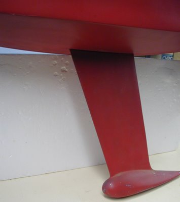
My main engine cooler consists of 60 of 5" channel welded to the hull. The water basically goes in one end of the channel cooler, runs its route through the channel, then returns back to the engine out the other end of the channel as cooled water. Ive seen other builders use split pipe on the hull, but for me the channel was easier to work with and Im pleased with its form. A young guy from our neighborhood was an engineering student at Utah State University ( Justine Gastrich), and needed a project during his senior year as a requirement for graduation. He calculated and designed the requirements for cooling my engine by using the 5" channel as a cooler. His report was very thorough and it was kind of neat seeing the boat build put to that use. The report that Justin developed was very much in line with all the rule of thumb designs other builders used, so I went with what Justin recommended.

I had to alter the engine a little to make the keel cooler work better but this was not a big deal. Because of the large volume of coolant I needed an expansion tank to give the coolant a place to go as things up to operating temperature. I also will use this expansion tank as the fill point to add coolant and a way to get the air out of the system. My engine modification was basically removing the fill cap from the engine heat exchanger and moving it to the expansion tank, then connecting the expansion tank back to the engine heat exchanger. The expansion tank is at a slightly higher elevation than the engines heat exchanger so getting the air out should be easier. Im using extended life coolant that is premixed using distilled water and coolant. Im also thinking of adding coolant filters as part of my system. Coolant filters need to be compatible with ones coolant ( either organic or non organic).

Ive had the engine running since Ive finished the keel cooler and all seems to be OK. I only had the engine running at a high idle but it did get up to operating temperature and stayed that way for the times I ran her. One good thing about the keel cooler is the ability to run the engine while on the hard.

I also decide to keel cool my air conditioners that Ill have on board. Im going to have two air conditioners ( one for the lower forward cabins, and one for the Salon and Wheelhouse). I think the lower AC unit will be around 12,000 btu, and the upper AC unit will be around 18,000 btu. I know of quite a few boats in our harbor that are always having problems with maintenance regarding their air conditioner from junk getting sucked up into the units. Keel cooling these air conditioners, while much more expensive, will eliminate most problems associated with a marine type air conditioner. While traveling down and aroun various harbors, Im amazed at the number of boaters that leave their air condtioners running while away from their boats for extended periods of time. I know of one boat that has been sunk due to the marine air conditioning unit failing and pumping water into the boat. While I dont think Ill leave the air conditioners runnig while Im not on the boat, with keel cooling I will have the ability to leave boat and not have to worry about the air conditioners. For the air conditoner coolers I used 2" sch. 40 pipe split in half and welded to the keel. Becuase the air conditioners will be used while the boat is sitting still I wanted to get the coolers as low in the water as I could. There is a cooler on each side of the hull for each air conditioner. The cooler for the forward cabins enters and leaves the hull amid ship, and the cooler for the upper areas of the boat enter and leave the hull more aft.

Again, the hardest part of building these coolers was air testing my welds. I air tested all the coolers to 10 psi. Tacking the coolers to the hull went relatively quickly with me having only a few hours in the fitting and tacking. Air testing on the other hand found me spending at least a full day fixing leaks for each cooler.

While these types of coolers might seem a little labor intensive in some folks eyes, the robust nature of the cooling systems adds to the boat as a whole in regards to function and safety. That robustness will also translate into lower operating costs in the future witch, in my opinion, will easily off set the cost of my labor to build these devices.

Conall

Do you find information about Boat Plans African Queen are you looking for? If not, below may help you find more information about the Boat Plans African Queen. Thank you for visiting, have a great day.
Read More..

Boat Plans Building | Sailing Model AMYA Star45 Class keel mount using keel trunk

| 0 komentar |

Boat Plans Building


Here is how John Fisher built two Star45 keel trunks. First he make a aluminum mandrel that is the same size and shape of the top of his keels. Next he waxed the aluminum and then put a single layer of wax paper over the mandrel.

He used a light spray of 3M 77 to stick the ends together on the second one. The first one had a pc of tape, which is now a part of the trunk.

The mandrel with waxed paper is wrapped with glass which he again used 3M 77 to hold in place. He has not verified that this doesnt have any long term effects to the glass so use at your own risk. John used 2 layers 3.2 oz glass with glass tape on the top and bottom edges to help add some stregth. Usually he would add kevlar, but that is not allowed in the stars. One the glass was in place John wet the whole thing with resin. If you dont have any way to vac bag the trunk, just let it cure and remove the mandrel. The trunk weighted in at 1 oz.

John has a food vacuum sealer so he put a release paper over the top (wax paper with holes in it), then breather cloth (he hasused paper towels in the past), and then into a food saver bag for the night.

To remove the mandrel he used a hammer and a vice. He knows that sounds severe, but that is what it took to get the mandrel back out. He started by placing the mandrel into a vice with smooth jaws. The jaws were just far enough apart that the aluminum would fit between them, but not the fiber glass wrap. Then he tapped the mandrel out. He points out how much force it took for him to get this apart so you can design your keel top with this in mind.

Photo 01- mandrel before prep
Photo 03 -mandrel with glass, ready for resin
Photo 04-keel trunk in food saver bag. You can see the resin going into the breather cloth.
Photo 05 - keel trunk off the mandrel, note the tape. 2nd trunk used3M 77 instead.
Photo 06 - Trunk on the keel.


The following picture shows the way that John aligned the keel on his second boat.
Since the keel is plate and 1/8" thick I laid a straight edge on it and
aligned it with the pc at the center of the transom. I did this on both
sides to make sure it is centered as well.

To capture the top of the keel box he added 2 1/8" X 3/8" spruce blocks
to the top of the keel trunk and glued them to the king plank. The photo also shows the glass tape He used to reinforce the
radio tray.


John Fisher photographer


===

here is an alternative keel trunk (from Uncle Dave)

I poked my camera down into the Sirius 45 and snapped a couple of pictures showing how the keel is attached to allow it to be removed and another installed.

The keel is a aluminum fin with my flat bottomed bulb. The keel trunk is assembled over the keel fin before mounting the trunk in the hull. The trunk is pretty simple. Two pieces of 1/8 ply on either side of the fin. Cut flush across the top of the fin. Height is determined by the amount of the fin to extend into the hull. Length is determined by the shadows or braces to support the fin. A filler pieced goes between the sides so that fin can be slid own and out of the trunk.

Before gluing the trunk up it is very important to coat the insides of the trunk to make the sides of the trunk as water resistant as you can. The the fun part is placing two mounting bolts through the sides of the trunk and thought the keel fin. I think the two bolts in the picture were 1/2 long 3/8 inch dia.

DLM_s45_trunk_a.jpg

I placed a heavy wire through the both the bolt heads so I could turn the nuts on the other side.

DLM_s45_trunk_b.jpg

With the nuts removed the two bolts simply push to one side and the keel fin mounted or removed as the case may be. In my models the height of the fin inside the model is low enough for a swing arm sail control to fit properly. I use Probar (now Dumas) SCUs.

Before building the deck I simply dropped the trunk (with keel fin) through the slot in the bottom of the hull so the trunk rests on the keelson. The hull being fiberglass the trunk if filleted with the bottom using some auto body resin-paste. I think I also used the resin paste to mount the keel trunk in my wooden models (memory escapes me its been years). The ends of the trunk are braced to the chine to with stand leverage forces from the heavy keel bulb and sailing stresses.

DLM_s45_trunk_d.jpg

When the two bolts are tightened they not only hold the keel in place they also pull the sides of the of the trunk tightly together. With the tight fit one should expect the keel fin may stick in the trunk if some sort of lubricant (silicone) isnt used.


Do you find information about Boat Plans Building are you looking for? If not, below may help you find more information about the Boat Plans Building. Thank you for visiting, have a great day.
Read More..

Boat Plans Butler | Didi 950 Keel Build by Howdy Bailey

| 0 komentar |

Boat Plans Butler


Howdy Bailey Yacht Services in Norfolk, Virginia, is building the keel for the Didi 950 project in Ohio. This one has a fixed keel that is supported by a steel box on the inside of the hull and which is bolted to the grid structure. The box also forms the engine beds, to concentrate these major weights in a tight area for low pitching characteristics in lumpy water.

Howdy and his staff are doing a masterful job of building this keel, which is assembled over a rigid skeleton of schedule pipes between end plates. The side plates are wrapped over the skeleton and plug welded.
One of Howdys staff welding the keel structure.
Completed keel skeleton with pre-formed side plates awaiting fitting.
Same stage, looking at the top plate.
The tubular internal skeleton, instead of transverse plate spacers, has multiple benefits. The pipes make the skeleton very rigid to resist twisting when fitting the side plates, they have soft surfaces to minimise hard spots that can distort the side plates, they present broad surfaces for plug welding the side plates and they serve as efficient heat sinks to draw heat away from the plug welds, minimising heat distortion.

The keel bolts bear on the keel box inside the hull, sandwiching the hull skin between the the two. Howdy Bailey Yacht Services fabricated the box as well, then shipped it to the builder. He has test-fitted the Beta 15hp motor on the beds ahead of installing the box into the boat. The following photos show the box with engine standing on the integral engine beds.
Didi 950 keel support box front view.
Beta 15 being test-fitted on the engine beds.
Aft view. The holes are for shaft, exhaust and ventilation.
Finding a suitably qualified engineering company to make the keel is often a worry for people considering building an offshore boat. Howdy and his staff have the experience and are available for this work.

To see more of our designs, visit our website at http://dixdesign.com/.

Do you find information about Boat Plans Butler are you looking for? If not, below may help you find more information about the Boat Plans Butler. Thank you for visiting, have a great day.
Read More..

Boat Plans Bruce Roberts | What the Saints did Next

| 0 komentar |

Boat Plans Bruce Roberts


The Saints are the people who live on St Helena Island, a remote island in the middle of the South Atlantic Ocean. They live on a mountain of rock that comes straight up out of the ocean, with steep cliffs all round and nary a beach to be seen. The terrain is very convoluted, with deep valleys and mountain passes. Until now, the only way to reach St Helena has been by boat or ship but soon an airport will be completed, making the island more accessible to others and opening up the world to the islanders. This is an interesting place to visit on Google Earth, to see how remote and inhospitable it is. The new airport can also be seen; consider the mammoth task that it must be taking to create it with the minimal resources available on the island. I imagine that much equipment and material has been shipped in over the past few years to accomplish this.
Saloon view of "Black Cat". Photo courtesy of What The Saints Did Next.
St Helena is the finishing point for the Governors Cup Yacht Race, sailed from False Bay Yacht Club in Simonstown on the western side of False Bay, South Africa, every two years. It was also the place to which Napoleon Bonaparte was banished for his second imprisonment. It was far enough away from anywhere else that he was not able to get up to any more mischief.

What The Saints Did Next is the blog for the island, which helps to keep the world up to date with whatever is happening on the island. The blog has a great post about "Black Cat" and her win in the most recent edition of the race. It includes an interview with the crew about the race and life aboard, as well as a bunch of really nice photos of "Black Cat" and crew.

I hope that I can be on "Black Cat" for her next voyage in this race. Visiting St Helena is on my bucket list as a place to visit. An ancestor of mine and the first Dix to settle in Cape Town arrived from St Helena. What he was doing there I dont know, possibly a soldier guarding Napoleon.

"Black Cat" is the prototype of my Didi 38 design and forerunner of all of my radius chine plywood designs. Visit our website at http://dixdesign.com for more info on my designs.

Do you find information about Boat Plans Bruce Roberts are you looking for? If not, below may help you find more information about the Boat Plans Bruce Roberts. Thank you for visiting, have a great day.
Read More..

Boat Plans Bolger | Weighing a keel bulb while attached to a boat

| 0 komentar |

Boat Plans Bolger


The Star 45 R/C Model Sail Boat - Builders Journal: Weighing a keel while attached to a boat

Weighing a keel while attached to a boat
From "Larry Ludwig"

"Weighing a keel while attached to a boat can be done with a high degree of accuracy. You can test this out on a boat with a removeable keel. Lay the boat on its side with the keelbulb on the scale with the keel parallel to the table. Then take the keel off and weight it and you will be amazed that they are nearly the same, as in within 95% or better."


Do you find information about Boat Plans Bolger are you looking for? If not, below may help you find more information about the Boat Plans Bolger. Thank you for visiting, have a great day.
Read More..

Boat Plans Aluminium Australia | S45 Construction John Fisher keel tubes

| 0 komentar |

Boat Plans Aluminium Australia


Photo sequence showing how John Fisher made his keel tubes. He was mounting a keel from CPM (David Ramos) with longer keel bolts so they will go through the deck when finished. He coated the brass rod with carnuba wax as a mold release.


To align the keel tubes John drills the holes in the center of the boat, this is easy to find since it is simply the middle of the king plank and the middle of the two keel planks. Then to align them so they are straight he placed a metal ruler along the two keel bolts or if a flat plate along the plate. Then look at where the end meets the transom. It should be off center by half the amount as the bolts/keel are thick.

John does this on both sides to make sure it is centered. Once the bottom is aligned he tacks it in place with CA, then verify the alignment at the deck the same way.


Do you find information about Boat Plans Aluminium Australia are you looking for? If not, below may help you find more information about the Boat Plans Aluminium Australia. Thank you for visiting, have a great day.
Read More..